Synchronous Transmission
Keeping 12m Arms Perfectly Aligned
The Challenge: Moving 12-Meter Arms Without Misalignment
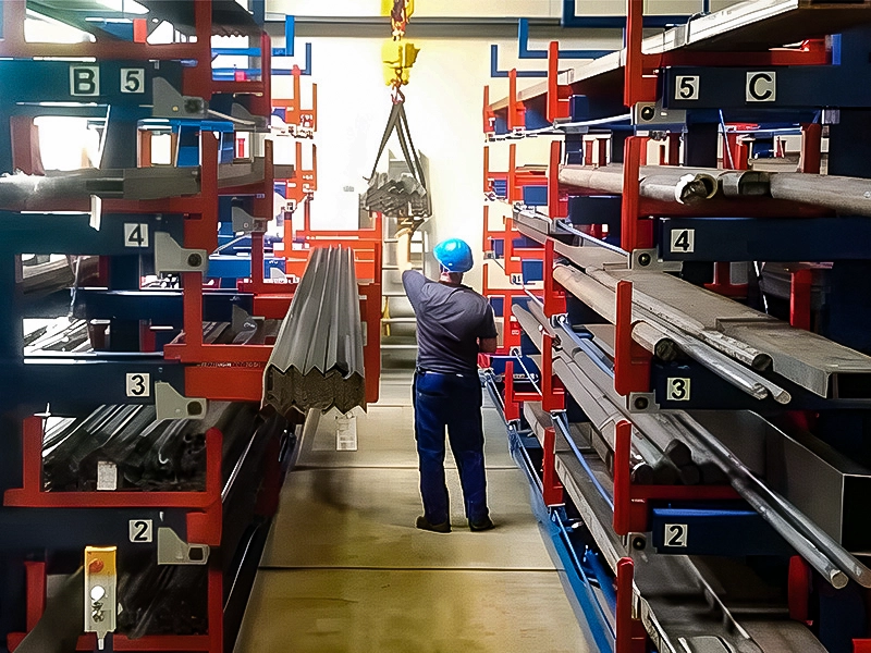
Picture a cantilever arm stretching 12 meters across a warehouse aisle — loaded with 3 to 5 tons of steel pipe or aluminum extrusion. Now imagine that arm needs to slide out smoothly, with both ends moving at exactly the same speed and reaching full extension at exactly the same moment. If one end leads by even a few millimeters per meter of travel, the arm binds, the gears jam, and you’ve got a serious mechanical problem on your hands.
This is the engineering challenge that synchronous transmission solves in telescopic cantilever rack systems. It’s the mechanism that makes single-operator control of multi-ton, multi-meter arms not just possible, but effortless.
How Synchronous Transmission Works
At its core, the system is elegantly simple — though the precision required to execute it is anything but.
The Rack and Pinion Foundation
Each cantilever arm rides on a set of gear racks (toothed steel bars) mounted along its underside. These mesh with pinion gears housed inside the upright columns. When the pinion rotates, it converts rotational motion into linear motion, pushing or pulling the arm horizontally. This rack-and-pinion mechanism is the same principle used in automotive steering systems — proven, reliable, and capable of handling enormous forces.
For a deeper look at this core mechanism, see our article on gear and rack mechanisms in telescopic shelving.
The Synchronized Transmission Shaft
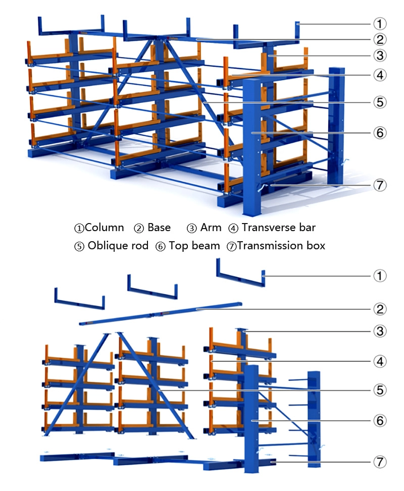
Here’s where it gets interesting. A telescopic cantilever rack with arms spanning 6 to 12 meters typically uses 4 to 8 upright columns to support each arm level. Each column has its own pinion gear engaging the arm’s rack. If these pinions rotated independently, the arm would inevitably skew — one side extending faster than the other.
The solution: a synchronized transmission shaft that physically connects all pinion gears on the same level across every column. When the operator turns the crank handle at one end, the shaft transmits torque instantaneously to every pinion along the entire span. All gears rotate at exactly the same speed, and the arm extends perfectly straight.
Think of it like a car’s axle connecting both wheels — except instead of two connection points, you might have four, six, or eight, all maintaining perfect rotational synchronization across a 12-meter span.
Why Laser Cutting Precision Is Non-Negotiable
The synchronized transmission shaft must pass through bearing housings in every upright column with near-perfect concentricity. If the shaft holes in adjacent columns are even slightly misaligned, the shaft will bind under load, creating enormous friction that makes the system impossible to operate by hand.
This is where laser cutting becomes critical. CFS uses laser cutting for all critical components — particularly the column plates where transmission shaft bearings are seated. Laser cutting achieves tolerances of ±0.1 mm or better, ensuring that when multiple columns are installed 1.5 to 3 meters apart, their shaft holes align perfectly.
For the TE Rack series (bolt-together assembly design), this precision is even more critical. Unlike the TC series where columns are factory-welded into rigid frames, TE Rack columns are assembled on-site from individual components. Every bolt hole, every bearing seat, every shaft coupling point must be laser-cut to exact specifications — because there’s no opportunity to “adjust” alignment through welding distortion correction.
As the CFS engineering team puts it: laser cutting precision is what makes “one hand moving 5 tons of cargo” physically possible.
Gear Phase Alignment: The Installation Detail That Makes or Breaks It
Even with perfectly manufactured components, installation can introduce synchronization errors if one critical detail is overlooked: gear phase alignment.
When the transmission shaft is connected across multiple columns, every pinion gear must engage its corresponding rack at exactly the same rotational position (phase). If one pinion is even one tooth off from the others, it will try to push its section of the arm slightly ahead or behind the rest. On a short arm, this might cause stiffness. On a 12-meter arm, it causes immediate binding and potential gear damage.
During installation, technicians must:
1. Pre-align all pinion gears to the same phase before tightening shaft couplings
2. Perform an unloaded extension test to verify smooth, even travel across the full stroke
3. Fine-adjust coupling positions if any binding or uneven resistance is detected
4. Lock all couplings with specified torque values once alignment is confirmed
This phase alignment step is documented in the Tcrack installation SOP as the single most critical assembly operation. Getting it wrong doesn’t just affect performance — it can cause cascading mechanical damage to gears, racks, and bearings.
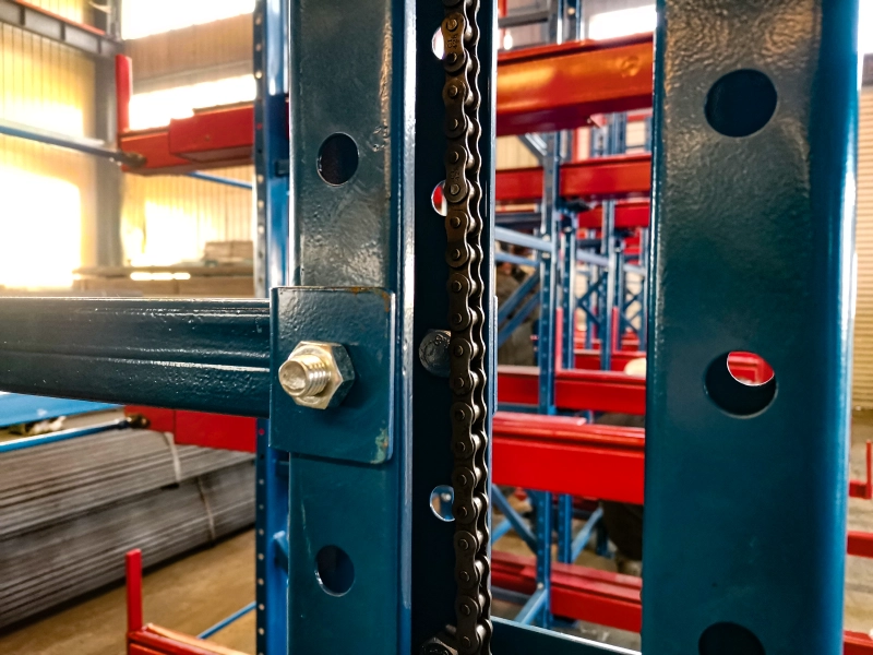
Chain Drive Integration for High Levels
For rack systems with 4 or 5 storage levels, the upper transmission shafts are too high for direct hand-crank operation. The solution is a chain drive system that transfers the drive point from the shaft height (potentially 3+ meters) down to an ergonomic operating height of 1.2 to 1.5 meters.
Chain wheels (sprockets) mounted on the transmission shaft connect via roller chain to a lower drive shaft accessible to the operator. The chain maintains the synchronous relationship — one turn of the lower crank produces exactly one turn of the upper transmission shaft, which simultaneously drives all pinions on that level.
For more on how this works in practice, see our detailed guide on chain drive systems for high-level rack access.
Manual vs Electric Drive: Same Synchronization, Different Power Source
Whether a Tcrack system uses manual crank operation or an electric motor, the synchronous transmission architecture remains identical. The motor simply replaces the human hand at the input end of the transmission shaft. This means:
- Manual systems can be retrofitted with electric drive without modifying the synchronization mechanism
- Electric systems maintain the same precision alignment requirements during installation
- Both systems benefit equally from the laser-cut precision of shaft bearing seats
The electric option becomes particularly valuable for high-frequency operations (20+ cycles per day) or very heavy loads where manual cranking, while mechanically possible, becomes physically demanding over a full shift.
Troubleshooting Synchronization Issues
When a previously smooth-operating rack develops stiffness or uneven arm travel, the synchronous transmission system is often the first place to investigate:
- Increased cranking resistance: Check lubrication on all gear-rack interfaces and shaft bearings. Old grease mixed with industrial dust creates an abrasive paste that dramatically increases friction.
- Uneven arm extension: Inspect shaft couplings for loosening. Vibration from daily operation can gradually back off coupling bolts, allowing phase drift between columns.
- Clicking or grinding sounds: Indicates gear-rack misalignment or worn teeth. Inspect for debris in the gear track and check rack straightness.
- Complete binding: Often caused by foundation settlement creating uneven column heights. The rigid transmission shaft cannot accommodate vertical misalignment between columns — even 2-3 mm of differential settlement can cause binding on long spans.
Regular preventive maintenance — weekly safety pin checks, monthly lubrication, quarterly structural audits — prevents most synchronization issues before they become operational problems. Refer to our warehouse safety checklist for a complete inspection schedule.
Precision Engineering That Disappears When It Works
The best compliment for a synchronous transmission system is that operators never think about it. They turn the crank, the arm glides out evenly, they load or unload material, and they crank it back. The thousands of engineering hours behind that simplicity — the laser-cut tolerances, the phase-aligned gears, the hardened transmission shafts — are invisible in daily use. And that’s exactly how it should be.
Want to See Synchronous Transmission in Action? Let our engineering team walk you through it.