Anti-Tipping Design
The Physics Behind Rack Stability
Why Anti-Tipping Design Is Non-Negotiable for Cantilever Racks
When a fully loaded cantilever arm extends outward carrying several tons of steel bars or aluminum extrusions, the laws of physics don’t take a break. The entire structure’s center of gravity shifts forward, generating an overturning moment that wants to pull the rack face-first onto the warehouse floor. Anti-tipping design is the engineering discipline that keeps that from happening — and it’s the single most critical safety feature in any telescopic cantilever rack system.
The Physics: Center of Gravity and Overturning Moment
Every object has a center of gravity (CG) — the single point where its entire weight effectively acts. For a telescopic cantilever rack at rest with all arms retracted, the CG sits comfortably within the footprint of the base frame. The rack is inherently stable, much like a closed filing cabinet.
The moment an operator extends a loaded arm, the equation changes dramatically. The heavy material — often 2,000 to 5,000 kg per level — moves outward beyond the base footprint. This creates an overturning moment, calculated as:
Overturning Moment = Load Weight × Horizontal Distance from Base Edge
For example, a 3,000 kg load on an arm extended 1.5 meters beyond the front base edge generates a 4,500 kg·m overturning moment. The rack’s base, anchor bolts, and dead weight must produce a restoring moment that exceeds this value — with a safety margin to spare.
How Tcrack Engineering Solves the Tipping Problem
CFS Tcrack racks employ a multi-layered approach to anti-tipping stability that goes well beyond simply bolting the rack to the floor.
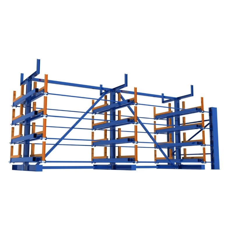
1. Engineered Base Frame Geometry
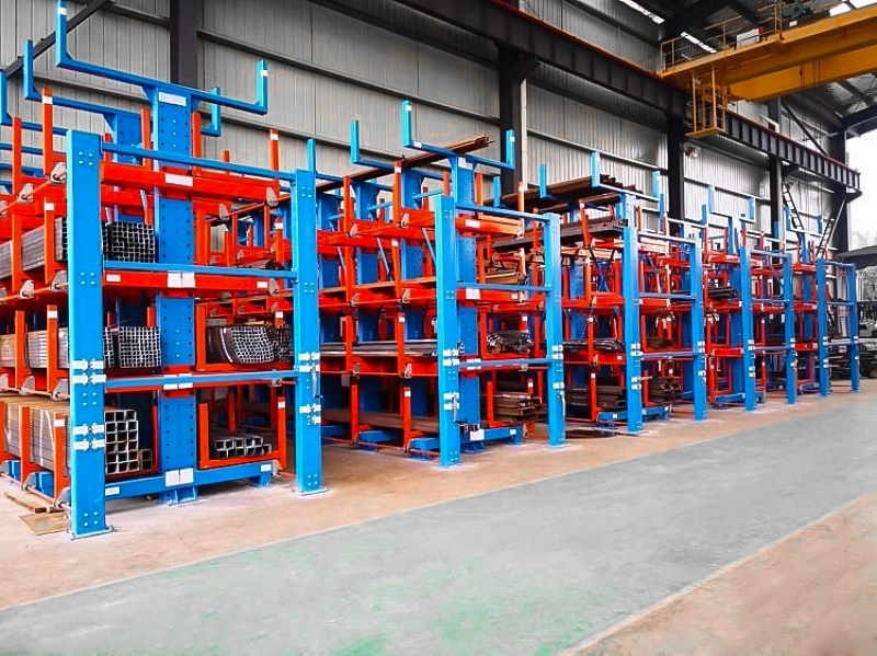
The base frame extends rearward (opposite the arm extension direction) to maximize the restoring moment arm. This rear extension acts as a counterweight lever. The deeper the base, the greater the restoring force — which is why Tcrack base depths are carefully calculated based on maximum rated load and arm extension length.
2. Anchor Bolt Systems
Chemical anchor bolts secure the rack to the concrete floor, providing tensile resistance against uplift forces on the rear base. These aren’t ordinary expansion anchors — they’re engineered for the specific pull-out forces generated during full-load arm extension. The concrete foundation itself must meet minimum thickness requirements (typically 150–200 mm reinforced concrete) to prevent anchor pull-through.
3. Safety Factor of 1.25×
Every Tcrack system is designed with a minimum 1.25× safety factor on rated load capacity. This means the structure can theoretically handle 25% more than its nameplate rating before reaching design limits. However, this margin exists to account for dynamic loads, minor overloading, and material fatigue over time — it is not an invitation to exceed rated capacity. As outlined in OSHA cantilever rack safety requirements, maximum safe load limits must be clearly posted and strictly observed.
4. Single-Level Operation Rule
This is arguably the most important operational safeguard. Tcrack’s anti-tipping calculations assume only one level is extended at any time. When two loaded levels extend simultaneously, the overturning moment roughly doubles — but the restoring moment stays the same. The CG shifts so far forward that no reasonable anchor system can prevent a catastrophic tip-over.
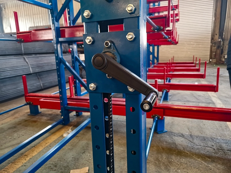
Some higher-end Tcrack models include an interlock mechanism that physically prevents a second level from extending while another is already out. For manual-operation models without interlocks, operator training and strict SOP compliance are the critical last line of defense.
Load Placement: Where You Put the Weight Matters
Even with perfect structural engineering, improper load placement can compromise stability. Tcrack loading standards follow these physics-based principles:
- Center of gravity toward the column: Material should be positioned with its weight concentrated toward the upright column, not at the arm tip. Tip-heavy loading maximizes the bending moment on the arm and increases the overturning tendency.
- Even distribution across arms: Spread the load across both support arms rather than concentrating weight on a single arm. Uneven loading creates torsional stress and asymmetric tipping forces.
- Heavy below, light above: When mixing material densities (e.g., solid bar stock and hollow tubes), always place heavier items on lower levels. This keeps the overall rack CG as low as possible, improving stability.
- Long below, short above: Mixed-length materials should follow the “long on bottom” rule to prevent shorter pieces from sliding through gaps and falling.
Shock Loads: The Hidden Tipping Risk
Static load calculations tell only part of the story. When an overhead crane drops material onto an extended arm — even from a height of just a few centimeters — the shock load can momentarily exceed the static load by 2–3×. This instantaneous force spike can overwhelm anchor bolt capacity and cause structural damage that compromises long-term stability.
Proper crane operation requires vertical lifting only (no side-pulling) and gentle placement. The crane hook must align directly over the material’s center of gravity before lifting. These aren’t just best practices — they’re essential to maintaining the anti-tipping safety envelope that engineers designed into the system. For more on integrating crane operations with rack systems, see our guide on overhead crane and telescopic rack combinations.
Floor and Foundation: The Unsung Hero
The most brilliantly engineered rack is only as stable as the floor it’s anchored to. Key foundation requirements include:
- Concrete thickness: Minimum 150 mm of reinforced concrete, with 200 mm recommended for racks rated above 3,000 kg per level
- Concrete strength: Minimum C25/30 grade (25 MPa compressive strength)
- Floor flatness: Deviations beyond ±5 mm per meter can create uneven loading on base frames, reducing effective anchor bolt capacity
- No cracks or voids: Existing floor damage near anchor points must be repaired before installation
A pre-installation floor survey is standard practice for any Tcrack deployment. Skipping this step is a false economy that can lead to anchor failures under load.
Inspection and Maintenance for Continued Stability
Anti-tipping safety isn’t a one-time achievement — it requires ongoing vigilance. A proper warehouse safety inspection checklist should include:
Weekly: Visual check of safety pins, limit bolts, and anchor bolt tightness
Monthly: Inspect base frame for cracks, deformation, or corrosion; verify all safety labels are legible
Quarterly: Full structural audit including arm deflection measurement and anchor bolt torque verification
Any rack showing visible deformation, loose anchors, or missing safety pins must be taken out of service immediately until repaired.
The Bottom Line: Physics Doesn’t Forgive Shortcuts
Anti-tipping design in telescopic cantilever racks is a precise balance of structural engineering, anchor systems, operational rules, and ongoing maintenance. Every element — from base frame geometry to the single-level operation rule — exists because the physics of overturning moments demands it. Cut one corner, and the safety margin shrinks. Cut two, and you’re gambling with lives and assets.
CFS Tcrack systems are engineered with these principles built in from the ground up. But engineering alone isn’t enough — proper installation, operator training, and disciplined maintenance complete the safety picture.
Need Help Designing a Stable, Safe Storage System? Get a free consultation today.