Understanding Gear & Rack Mechanism
in Telescopic Shelving
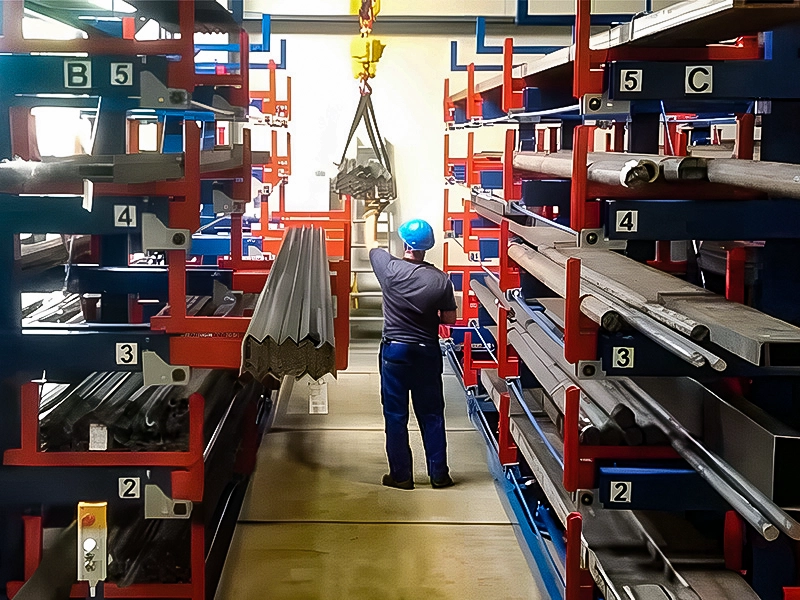
Every telescopic cantilever rack relies on one elegant mechanical principle: the gear and rack (rack and pinion) mechanism. It is this precision-engineered drivetrain that allows a single operator to slide multi-ton loads in and out of storage — no forklift required. In this guide we break down exactly how the system works, why it matters, and what to look for when specifying a telescopic rack for your facility.
What Is a Rack and Pinion Mechanism?
A rack and pinion converts rotational motion into linear motion. The pinion is a small cylindrical gear; the rack is a flat, toothed bar. When the pinion turns, its teeth mesh with the rack’s teeth and push the rack in a straight line. It is the same principle used in automotive steering columns, CNC machine tables, and railway cog systems — proven, reliable, and capable of transmitting very high forces with minimal friction loss.
In a telescopic cantilever rack the rack is mounted to the underside of each cantilever arm, while the pinion sits inside the upright column. Turning the operating handle (or engaging the electric motor) rotates the pinion, which drives the arm outward until it reaches full 100% extension beyond the base frame.
How the Drivetrain Works Inside a Telescopic Rack
Gear and Rack (Rack & Pinion)
Each storage level has a hardened alloy-steel rack bolted to the underside of the cantilever beam. The rack’s module (tooth size) is calculated to withstand the shear forces generated when the arm is fully loaded — often 3,000 kg or more per level. Inside the column, a matching pinion gear meshes with the rack. Because the gear ratio provides significant mechanical advantage, the input torque required at the handle is remarkably low: a single person can move several tons of steel, aluminum, or lumber with one hand.
Transmission Shaft — Keeping Both Ends in Sync
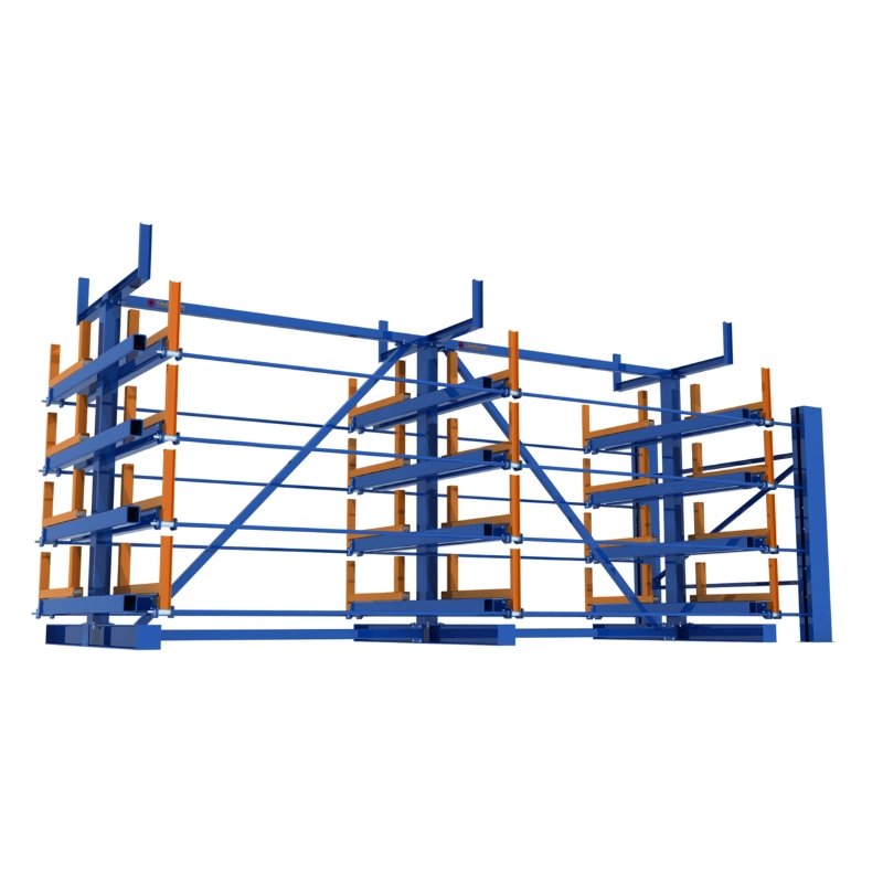
Most industrial racks span 6 to 12 meters between uprights. If only one end of the arm were driven, the far end would lag behind, causing the arm to bind or skew. The solution is a synchronous transmission shaft that connects the pinion gears in every upright along the same level. When the operator turns the handle at one end, torque is transmitted instantly through the shaft to all uprights, ensuring the arm extends perfectly parallel.
Manufacturing tolerance is critical here. The bore holes for the transmission shaft must be laser-cut to guarantee concentricity across multiple uprights. Even a fraction of a millimeter of misalignment can cause binding under load — which is why CFS uses laser cutting on all critical connection points for both the TC Rack (welded series) and the TE Rack (assembled series).
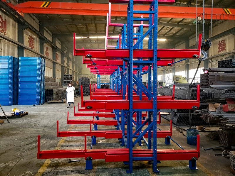
Chain Drive for High-Level Access
Racks with four, five, or even six storage levels present an obvious challenge: the upper arms are well above head height. Climbing a ladder to crank each level is slow and dangerous. The answer is a chain drive system. A chain wheel at the top of each upright connects via roller chain to a drive point at ergonomic height — typically 1.2 m to 1.5 m above the floor. The operator simply turns the handle at waist level, and the chain transmits the force upward to the pinion gear on the target level. No ladders, no platforms, no risk of falls.
Bearings — The Unsung Heroes
Every cantilever arm rides on heavy-duty ball bearings housed in sealed bearing blocks. The seals keep out industrial dust, metal shavings, and moisture, while the bearings themselves reduce rolling friction to near zero. This is a key reason why a loaded arm moves so smoothly: the combination of low-friction bearings and high-ratio gearing means the operator feels almost no resistance, even with a full load of steel plate or bundled pipe.
Why Gear and Rack Beats Other Drive Methods
Some competing systems use hydraulic cylinders or simple roller slides. Here is why rack and pinion remains the gold standard for telescopic cantilever racks:
- Precision: Tooth-to-tooth engagement gives exact positional control. The arm stops exactly where you stop cranking — no drift, no creep.
- Mechanical advantage: Gear ratios of 20:1 or higher let one person move loads that would otherwise require powered equipment.
- Durability: Hardened alloy-steel gears and racks have a service life measured in decades, not years. There are no hydraulic seals to leak, no fluid to change.
- Simplicity: Fewer moving parts means fewer failure modes. Maintenance is limited to periodic greasing and bolt checks.
- Bi-directional: The same handle extends and retracts the arm. Reverse the rotation, reverse the motion.
Manual Crank vs. Electric Motor Operation
The gear and rack mechanism supports both manual and powered input:
- Manual crank (rocking handle): The operator inserts a removable handle into the transmission shaft coupling and turns it by hand. Ideal for facilities with moderate access frequency — say, 10–20 operations per shift. Zero electricity cost, zero wiring, and the arm can always be operated even during a power outage.
- Electric motor with remote control: For high-frequency operations or very heavy loads, an electric gearmotor replaces the manual handle. The operator presses a button on a pendant or wireless remote, and the motor drives the pinion at a controlled speed. Safety limit switches stop the arm automatically at full extension and full retraction.
Both options use the same underlying rack and pinion drivetrain — the only difference is the input source. Many customers start with manual operation and retrofit electric motors later as throughput increases. Learn more in our detailed guide to how telescopic racks work.
Safety Features Built Into the Mechanism
The gear and rack system is not just about motion — it is also about control and safety:
- Stop blocks (limit devices): Physical stops at each end of the rack prevent the arm from traveling beyond its designed stroke. The arm cannot over-extend or over-retract.
- Safety pins: Once the arm is fully retracted (or fully extended for loading), a locking pin is inserted to hold it in position. This prevents accidental movement caused by floor vibration, seismic activity, or an inadvertent bump.
- Single-level interlock (select models): On higher-end configurations, a mechanical interlock prevents more than one level from being extended at the same time. This is a critical anti-tipping safeguard — extending two loaded levels simultaneously shifts the center of gravity beyond the base footprint and can cause the entire rack to overturn.
For a complete overview of operational safety rules, see our FAQ page and installation guide.
Maintenance Tips for the Gear and Rack System
Keeping the drivetrain in top condition is straightforward:
Weekly: Visually inspect the rack teeth and pinion for chips, cracks, or foreign objects lodged between teeth.
Monthly: Clean old grease and accumulated metal dust from the rack, pinion, chain, and bearing housings. Apply fresh lithium-based grease. Never apply new grease over old contaminated grease — the trapped particles act as an abrasive paste that accelerates wear.
Monthly: Check all structural bolts (especially on TE series assembled joints) and anchor bolts with a torque wrench. Vibration from daily operations can loosen fasteners over time.
Semi-annually: Use a spirit level to check cantilever arms for permanent deflection. Any visible sag indicates overloading history and should be investigated before continued use.
A well-maintained rack and pinion system will deliver reliable service for 20 years or more — far outlasting hydraulic or pneumatic alternatives.
Choosing the Right Rack System for Your Application
The gear and rack mechanism is common to both CFS product families, but the surrounding structure differs:
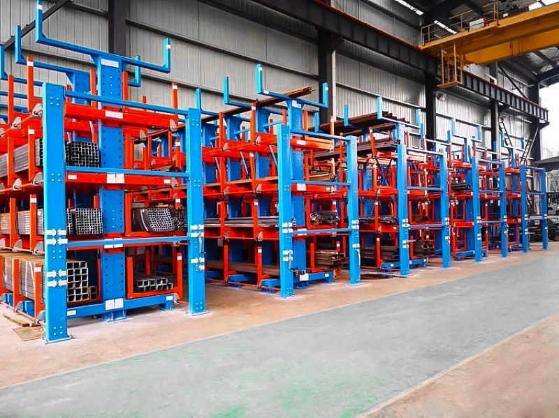
- TC Rack (welded): Arms are fully welded to the uprights. Maximum structural rigidity. Best for high-frequency, heavy-duty environments like steel service centers. Ships as large assemblies — ideal when the installation site is accessible by flatbed truck.
- TE Rack (assembled): Arms connect to double uprights via precision brackets. Can be flat-packed into standard 40HQ containers, dramatically reducing international shipping costs. Perfect for export projects and facilities with limited crane access during installation.
Both series share the same rack and pinion core, the same bearing quality, and the same operational principle. The choice comes down to logistics, installation constraints, and budget. Our product overview covers the full comparison.
Ready to Specify a Telescopic Rack System? Tell us about your storage challenge.